In Part 1 of the Wireless Microphones piece, I described wireless mic limitations, preferred locations of mic and receiver, RF link budgets and antenna polarization. In Part 2, we'll cover radio frequency names, antenna patterns and compression/expansion circuits.
Superlatives
Us techno-geeks are quick to toss out acronyms like VHF and UHF without a care, hoping that no one will bother to ask why a user might choose VHF or UHF as the frequency band for transmission. Starting with HF (high frequency), we move up to VHF (very high frequency), then on to UHF (ultra high frequency), then to SHF (super high frequency) and, believe it or not, EHF (extremely high frequency). Each of these high-frequency superlatives stand for a range of frequencies, or bandwidth. HF has 3 megahertz to 30 megahertz, VHF has 30 megahertz to 300 megahertz, UHF has 300 megahertz to 3 gigahertz, SHF has 3 gigahertz to 30 gigahertz, and EHF has 30 gigahertz to 300 gigahertz. And these are all waves per second of radiated electromagnetic energy, better known as radio frequencies (RF). The reason I am blathering about Hertzian waves and superlatives is that these waves travel from transmit antennas to receiver antennas at 300,000,000 meters per second. If your transmit frequency is 300MHz, then a new wave starts just as the previous wave expands to one meter beyond the antenna. Much like sound waves, the one meter is a "wavelength".
Antenna Theory
To cut to the chase on antenna theory for wireless mics, most wireless mics and wireless mic receivers use "wire antennas" cut to a quarter wavelength of their nominal transmit frequency bandwidth. That is why VHF antennas tend to be the telescoping whip types at the receiver and floppy wires at the mic or belt pack. UHF antennas are much shorter and tend to be nontelescoping rods on both the wireless mic and receiver. The reason for only a quarter of their wavelength in size is that they use the "groundplane" to bounce and balance the RF waves for efficient transmission and reception. See Figs. 1 and 2 for depictions of a UHF wireless mic and receiver.
The groundplane for the mic receiver is the chassis and any other conductive rackmounting materials. On most wireless mics, the metal mic grip is the ground plane. By designing the quarter wave antennas and a quarter wave or more of nearby groundplane, the RF waves can be transmitted and received well. But the mechanical configuration of the wire/rod/whip antenna and the groundplane defines the way most of the RF energy travels to/from the antenna. This yellow defined area in the figures is the antenna pattern of best transmission and reception and looks a lot like mic and speaker patterns. Note the steep "nulls" at the ends of the wire antennas where not much energy is transmitted or received. And knowing the nulls is what I want you to take away from this diagram so you know not to locate a receiver/transmitter RF path where these nulls are occurring.
This means the receivers should be not high above the stage, or well below the stage. Also, do not place the receivers down the "boresight" line of the typical mic-handling angle (down-front, behind-above). But beyond these few null points, there leaves a lot of front/back/sides locating of receivers for good reception. As I mentioned in Part 1 of wireless mics, you typically have little to no control of how the "artist" handles the wireless mic, but you can locate the receivers reasonably close and out of the null paths.
The Ol' Squeeze-Ola
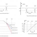
To get from the microphone diaphragm to the console, wired mics have–at most–a transformer and wire in the path. But most wireless mics have amplifiers, VHF or UHF transmitters and receivers with frequency modulation (FM) to keep the static out. But through the air, FM transmission only has about 50dB signal to noise ratio, and most microphones require about a 90dB or better signal to noise ratio to be at parity with wired mics. To get the extra tens of decibels of dynamic range, a compressor circuit in the wireless mic squeezes the 90dB down into the 50dB FM channel. At the receiver, the reverse must be done by expanding the 50dB back to 90dB with an expander circuit. Fig. 3 shows a typical block diagram of wireless mic and receiver signal paths.
While compression and expansion circuits are well-known in audio gear, making a very high-quality compressorintegrated circuit to fit inside a small microphone is quite a challenge. Then add problems like very small battery voltages, and the compressor must lightly "sip" power from the same battery to not drastically decrease talk time on the wireless mic. This is why most wireless mic manufacturers spend precious engineering resources developing, and marketing resources advertising, that their compressors and expanders are the best, and make comparison to wired mics. So note those bandwidths, distortions and dynamic range specifications, as well as battery life, when comparing wireless mic systems.
Many years ago, VHF wireless mics were the only affordable option. But as the RF electronic technology improved, UHF mics came about. UHF wireless systems offered smaller antennas and a less crowded frequency spectrum to be exploited. But as I mentioned in Part 1 on wireless mics, higher frequencies like UHF undergo more attenuation when penetrating performers in the path of the receiver. For awhile, this oddly made VHF wireless less expensive and more reliable, until UHF receiver technology could handle weaker UHF signals. Today, only a few VHF wireless mic offerings are still available, mostly for the cost-conscious music industry (MI) buyer who can live with the bigger antennas.


