In the past couple of years, digital speaker processors have gone from early adopter stuff for the rich and touring to too economical not to have. Not so long ago, good soundcos were racking and stacking analog crossovers, signal limiters and equalizers to create the secret sauce known as a drive rack. And in that chain of processing, everything had to be set just right or the show had no headroom and speaker drivers were in peril of death-by-amplifier. Now fast-forward to today, and we can purchase decent quality sub-$800 digital speaker processors in 2-by-6 or 4-by-8 configurations and feel the love. However, newcomers are still intimidated by the user interfaces, sending prayers to the manufacturer's help line for presets to their chosen set of speakers and passive/bi/tri-amp patching configurations. And woe to those who bought brand X's speaker processor to power brand Y's speakers. And expect charity on brand X's help line? Good luck with all that…
I find that, even with a single brand for both processor and speakers, there is not always the nirvana that newbie digital processor operators expect. The pre-settings may be adequate, but the equalizer settings are usually tuned to what the brand's application engineer thinks of as his favorite "room EQ." While I feel that absolute flat frequency response out of the speakers is not the best end goal, it is a good starting point and probably something that factory presets should be offered as. Myself, I look at the 100dB to 110dB equal loudness curves on the Fletcher-Munson chart (the chart in the March 2003 Theory and Practice column) and note that I should put a couple extra dB dip in the 3 to 5kHz range to make the perceived speaker output sound flat. The good news is that most hi-mid drivers have plenty of efficiency in the 3 to 5kHz passband to trim out using the new EQ capabilities of the digital speaker processor.
Flying Without Autopilot
The rest of this column consists of tips to create your own personal speaker processor presets and using an example from my personal experience. The first thing is to choose your speaker drive configuration. Many newbies will just replace ye olde analog crossover that split the subs and passive driven tops, and that is a good comfort configuration to start with. And if your LF drivers on your tops are 15 inches and you have 18-inch drivers on the subs, start with the tried and true 80Hz to 100Hz crossover setup and match up cabinet sensitivities at the crossover frequency area (typically a modest bump up on the sub feed). And just like good analog crossovers, start with the 24dB Linkewitz-Riley crossover filters at the chosen frequency.
If you instead have 12-inch LF drivers on your top boxes, then do the same as before but in the 100Hz to 125Hz frequency band. Now, after doing the baby steps in the speaker crossover menu choices, you are ready to play equalizer filter games in the sub and top box passbands. And I will expound on this more later in this column. If your top boxes are two-way (HF horns and LF), then better speaker brands should permit a bi-amp capability via a back panel switch or minor jack panel surgery. You should have the existing factory recommended passive crossover frequency points if possible. If not, you can approximate these points based on the size of HF driver you have.
Your typical pro-grade 4-inch diaphragm/ 2-inch throat HF driver should have a crossover point near 1000Hz. For a pro-grade 3-inch diaphragm/1.4-inch throat HF driver, 1250Hz is a good crossover point. And for a pro-grade 2-inch diaphragm/1-inch throat HF driver in bi-amp mode, 2.5kHz is nice for a crossover point. There are smaller HF driver sizes, but I would be amazed if they have biamp provisions; as these small HF drives are typically found in budget MI cabinets.
So easing into a three-way system, I would recommend keeping your subs set up just like the previous sub/top crossover point, but now splitting the top boxes by adding a mid/high crossover point for bi-amp drive. For example, my EV QRx218/QRx212 rig is crossed at 125Hz and 1250Hz. No polarity flips are needed, but adding 5.5 inches of voice coil delay on the mids and sub passbands aligns the HF crossover point phasing between mids and highs. That 5.5 inches of delay actually is 0.417 milliseconds of delay time when divided by the nominal speed of sound at approximately 1100 feet per second. Typically, the factory will recommend a delay, but you could take an approximate MF to HF phase distance measurement if none is provided.
The Three-Way Exception
With most mid-market three-way cabinets, such as a 15-inch LF plus 8-inch MF plus 1-inch HF horn, the top boxes do not have tri-amp capability, but offer bi-amp capability with the passive MF/HF crossover left intact. What this means is that you have only the flexibility to choose the LF/MF frequency crossover point on the three-way top box, and the gain, polarity/phase and major HF equalization is provided for you. And that LF/MF crossover frequency should pretty much stay near where the manufacturer recommends it to be set, lest you stray too much and toast the mid-frequency driver (which is typical).
If you have the luck and capability to have a 4-by-8 speaker processor to drive subs and a tri-amp top system, then you better abide by manufacturers' recommendations on crossover points and time delays. But the good news is that you now have the flexibility to fine tune the equalization across the whole audio frequency range — and then fine tune the power amp limiters for best headroom capability.
Equalization
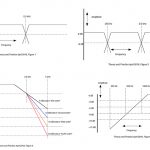
While most digital speaker processors have a graphic equalizer feature before the crossover signal chain, I recommend leaving it alone. Instead, focus on targets of opportunity using the parametric EQs for each post-crossover passband output path. Now I am going to commit heresy by recommending that you at least borrow some kind of noise generator/ RTA display device to stimulate, measure and smooth things up the first time you get a new set of speakers. At this point, you should feel that you can power up the drive train (processor, amps) and inject fairly low volumes of pink noise to set the passband gains. If the speaker documentation is lost or not trustable, start with subs and LF/MF sections at unity gain boost/cut (i.e., 0dB) and drop the HF section gain by 6dB. You should have much flatter responses on the RTA, but ugliness in the 3 to 5kHz band peaking, dropoff above 6kHz and possibly some modest dips or peaks in the 150Hz to 1kHz area. Figure 1 shows a typical RTA/pink noise spectrum plot if everything starts at unity gain passbands.
Ideally, you want your SIAsoft SMAART Live or Spectrafoo noise/RTA package to show you these nice peaks and dips. My first attack on EQs is actually at the ends of the audio bands by choosing something like 40Hz and 16kHz shelving equalization with a Butterworth three-pole (18dB/octave) slope roll off for rumble and hiss that the drivers or cabinet can not reproduce. After this, I identify my sub cabinet — 10dB bottom end frequency response (typically in the 40 to 50Hz range for dual 18-inch subs) — and place a parametric peak filter just above that drop off to lend support in 40 to 60Hz range, which tends to need a bit of help. The boost may only be 2–6dB, and the bandwidth a few tens of Hz wide (e.g. 40 to 60Hz centered at 50Hz), but that touch of bottom will add immense fidelity to kick drums and bass guitar reproduction besides the expected chest thump at 80Hz.
Going up to the low presence band at 3–5kHz, most HF drivers have a resonance peak in here that needs a few dB of drop at a moderate bandwidth to flatten things up, or in my case, place an additional mild dip here for the equal loudness compensation. After 6kHz, you may realize you are going to need a whole bunch of gain eased on as 6kHz builds towards 15kHz. There are a couple of ways to get here, depending of the EQ capabilities of digital speaker processors. If you have a shelving filter capability in the HF besides the previously mentioned 16kHz drop filter, start it at 12kHz with a 6dB gain and one-pole slope (6dB/ octave). Then adjust the gain and frequency to get the desired flatness. Do not get greedy with 1.4-inch and 2-inch throat HF drivers, as 10 to 12kHz may be all you can expect with those larger diaphragm masses, and piling gain much beyond 10dB at 12kHz is just a recipe for diaphragm burnout. But a 1- inch throat driver should easily make 14kHz without goosing the gains too much.
If you do not have a shelving capability, try using a parametric EQ boost centered at 14kHz with a one-octave bandwidth. Be prepared to slop on a 6–12dB gain peak to flatten up the HF, and even tack on another filter in the 6–12kHz region for smoothness (boost or dip). Lastly, attack modest dips or peaks in the mid bands using the RTA to seek them out, and flatten them up. Beware that imperfect shop testing acoustics may be the root of these bumps, so move the RTA mic placement closer/further to verify the peak/dip is stationary and not just coming from the floor/wall/ceiling reflections.
Limiters
If you practice safe amplifier sizing and same gains for each passband, as mentioned in previous Theory and Practice columns, then your passband limiter settings will track your passband gains. For example, all amplifiers have 40V/V gains (+32dB) and full power input ratings at about +7 to +9dBu levels. So from Figure 1, I limit the mids at +7dBu, subs at +9dBu and tops at +1dBu tracking the passband gains. The challenge is to doublecheck your choices by knowing the passband driver program power ratings and amplifier power ratings. The idea is that limiter clamps at or before the amplifier runs out of headroom, and the drivers get all the power they need for near program ratings. Note that with all that filter gain in the HF passband, you may limit first at HF before the mids and subs get going. That may be an indication to back off on the HF filter boosts and suffer a little less highs as things get loud.
Test your theory, contact Mark at marka@ fohonline.com.


