In previous columns, we discussed speaker processor operation and how to phase/time match mid-range drivers to high-frequency drivers. And we went through the various crossover filters for differing size high-frequency throats and diaphragms. But this time, I want to focus on frequency response adjustment of high-frequency drivers, as it is crucial to the quality of the sound system.
History
Before loudspeaker digital signal processing, all we had were analog crossovers and graphic/parametric equalizers. Each engineer that approached front of house had his or her “secret sauce” equalization curve that made things perfect. Those who knew less delved into the “hunt-and-hack” process on graphic equalizers until “they” thought it sounded as good as it would get. Such was the ego driven curse of guest engineers on provided sound systems.
Now the owner/operators of those sound systems generally knew where all the “bodies were buried” in terms of speaker cabinet driver knowledge, any passive crossover networks inside the cabinets and the electronic crossover settings back at the amp racks that kept things from blowing up. When these system tech operators got to mix at FOH, a few smooth equalizer curves were set, and the attention was back on the act and the mix at the console.
Today, with Digital Signal Processing (DSP)-based speaker controllers containing all the signal processing features like gains, delays and filters for both crossover and driver/cabinet optimization, the system tech can just let the FOH main mix graphic equalizer stay flat. Then the guest engineers can attempt to polish the overall mix from what the provider thought was perfection.
The Goal
So as an owner/operator of a sound company, you need to be given the knowledge to shop-tweak the rigs you own to optimum flatness before your customer/guest engineers mess with the equalizer. And nothing repels a guest engineer from the FOH equalizer more than a great sounding rig at the FOH position. But the crucial system setup aspect is getting the 1 kHz and up, high-frequency filtering perfect beforehand.
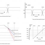
Before we get down and dirty on the parametric filters, Figure 1 shows what we are after in terms of a “flat” system. Note that the figure is the 110 and 120 dB SPL loudness curve from the Fletcher-Munson chart on human hearing. I narrowed the chart to see only the high-frequency range, and we should note two things. First is that the broad dip at around 3 kHz means that we need to drop some of this lower presence band as it represents the classic “ice-pick-in-the-ears” frequencies that we humans are over-sensitive to. By making this mid dip, we are “darkening” the mix a touch for music performances, but if the gig is mostly just speeches (public addresses) then the dip can be lessened to enhance speaker diction. Note that the mid-band dip is about 8 to 10 dB down from 1 kHz at these loudness levels, so it is a significant equalization shift.
The second thing to note is that coming out of that lower presence dip (1.5 kHz to 6 kHz,) we suddenly need another 5 dB of boost in the 9 kHz and up band. This is hard to achieve in most large sound systems, and many rigs just give up on getting this boost, especially in outdoor systems. For indoor venues, the newer speaker cabinets, and especially line arrays, are allowing for very good last octave of HF coverage by using smaller drivers on phased horns or with ribbon drivers.
Gazintas and Gozatas
Figure 1 defines what we want coming out of the speaker stacks, or Gozata (going out of) the system. The challenge is next brought to the high-frequency drivers and their capabilities. Once we know the Gozata and the driver response, we can then provide the correct speaker processor settings for the Gazinta (goes into) to the amplifiers and speaker cabinets. Figure 2 shows a typical 1.4-inch throat/3-inch diaphragm, high-frequency driver frequency response attached to a medium throw horn.
In Figure 2, the first item of note is the efficient lower presence frequency response center about at 2 kHz. This is counterproductive to our Figure 1 desire to darken up this band. The next item is the gentle slope downward from 4 kHz out to about 13 kHz and then a real drop afterwards. This drop spans 20 dB with the most gentle part about a 6 dB/octave (single pole) in the 5 kHz to 10 kHz octave. This drop off shows the classic compression driver loss of efficiency with frequency, and where caution needs to be exercised on choosing the upper corner frequency of reproduction.
Because of the relatively large size of the HF driver element, I the recommended 1.2 kHz point for the crossover point, to implement a 12 kHz Butterworth, 2-pole (12 dB/octave), high-pass filter. The 12 kHz choice is important since flattening up the drop in the 5 kHz to 12 kHz requires a lot of gain in the 10 kHz area. Then there is desire for another 5 dB in this frequency band from Figure 1 on top of correcting the driver response. This means there is a lot of amplifier power being used to push the diaphragm and voice coil mass around in the 10 kHz area compared to the lower frequencies. And if I wanted frequency response beyond 12 kHz, I would risk blowing up the driver via heating to overcome the greater than 20 dB mechnical/acoustic losses at these high frequencies.
The Setup
Without getting cute on filter settings for this Figure1/Figure2 system, I would first choose to set the crossover at 1.2 kHz using a 4-pole Linkwitz-Riley filter, and high-pass the HF band with a 12 kHz, 2-pole Butterworth filter. I would then take advantage of these modern DSP speaker processors by using the four or more parametric filters they offer per pass-band. The order is not critical, but I would implement the cuts first by choosing them in frequency order. So my first cut would be at 1.8 kHz with -5 dB shaved over a 1.8 kHz bandwidth just to flatten up the “horn honk” first and further cut by inserting the 3.2 kHz, -10 dB parametric filter with a bandwidth of around 3.2 kHz.
When looking at the Figure 2 chart, also note that this driver showing a sensitivity beyond 110 dB SPL, and we shaved off the 5 dB of honk to leave a 110 dB response flattened from the 1.2 kHz to 4.5 kHz band. This means that at the speaker processor we will likely peel off another 8 to 12 dB of pass-band overall gain to sensitivity match the HF to the MF or LF driver pass-bands. Since the high-frequency filters and gain have all been attenuating signal, we can now start adding gain back in the upper parts of the high-frequency band.
A couple approaches are possible, depending on the capabilities of the speaker processor used. The easiest would be to just add a parametric filter at 12 kHz with about 15 dB of gain and a nominal bandwidth (-3 dB points) of 4 kHz to set the slopes to be gentle in the 5 kHz to 10 kHz. Above 12 kHz is already handled with the previous Butterworth high-pass filter, so there is no concern above the filter center frequency.
Some speaker processors will allow non parametric pass filters besides the parametric filters. In this case, a low-pass shelving filter at 12 kHz with about a 6 to 10 dB/octave rolloff will be a good substitute. For those who have parametric filters to spare, a two parametric filter approach can be used with a gentle filter centered around 8.5 kHz with an 12 dB boost and a 6 kHz bandwidth. The second parametric would then be sharper at about 12 kHz with about 6 dB more boost at 2 kHz bandwidth. This would also solve the +5 dB Fletcher-Munson curve boost needed above the 9 kHz frequencies.
Contact Mark at marka@fohonline.com


