Someone recently asked me to explain dynamic range. Answering this question reminded me of a quote attributed to Supreme Court Justice Potter Stewart regarding obscenity: “I know it when I see it.” In describing dynamic range, I can substitute the word “hear” for “see.” Nevertheless, my editor here at FOH would undoubtedly prefer a more concrete explanation.
By Definition
Let’s start with a very basic definition of dynamic range: the variation of volume levels in a musical performance, from softest to loudest. That’s easy enough. Things get complicated when we add audio gear into the mix, figuratively (or literally). One of the best explanations I can think of will require Mr. Peabody to set our Wayback Machine to the mid-1950’s.
This was a time when analog tape was the recording medium of choice. Engineers were struggling to record orchestral performances onto tape for release on vinyl. Here’s the problem: an orchestra can exhibit a huge dynamic range, easily in the vicinity of 80 dB, sometimes more. The dynamic range of analog tape at this time was probably about 50 to 55 dB (though it eventually increased through the use of improved tape formulations and the introduction of noise reduction).
Why was the dynamic range of tape limited? Analog tape has two distinct signal “boundaries.” At the bottom, we have tape hiss, which is our noise floor — the lowest amount of noise that can ever be present in the recording. If we have no signal on the tape, when we play that tape we will hear hiss due to the inherent noise properties of analog tape. At some point, the orchestra gets so quiet that the sound it produces is masked by tape hiss. To compensate, we bring up the recording level. And now we face the other boundary: saturation. At some point, the orchestra gets so loud that the signal “saturates” the tape, causing distortion or clipping.
If the working area between analog tape hiss and clipping is around 50 dB, but the orchestra has a dynamic range of 80 dB, we have to figure out a way to “fit” the orchestra onto tape. First we had “gain riding” whereby an engineer followed the musical score, raising the input level to the tape machine during soft passages to overcome tape hiss, and lowering the input level during loud passages to avoid distortion. (This is manual compression. Later on we’d built compressors and limiters). The engineer’s target level is 0 on a VU meter — where experience shows the signal is loud enough to comfortably overcome hiss, but low enough to comfortably avoid distortion. Zero on a VU meter is referred to as “operating level.” For you newbies, 0 VU does not mean “no signal” — in the pro audio world, it means a signal level of roughly 1.23 volts, a.k.a. “nominal” signal level, or +4 dBu.
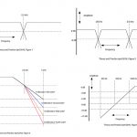
We have now identified three important markers in dynamic range: Noise floor, operating level and clipping. If we look at these three points on a vertical scale (see Fig. 1), we come up with two very important audio concepts: Signal-to-noise (S/N) ratio and headroom. Signal-to-noise ratio is the space (in dB) between operating level and the noise floor. A higher S/N ratio means we hear less noise. Headroom is the space between operating level and clipping. More headroom means we worry less about loud transient sounds overloading our audio circuits and causing distortion. The signal-to-noise ratio plus headroom always equals dynamic range.
Got that? Good, because now Mr. Peabody is going to return us to 2015, when digital audio gear makes everything sound and look different. First big difference: tape hiss is no longer an issue. Blessed are you who will never worry about a solo violin disappearing into tape hiss, and incur the wrath of the violinist. The noise floor in a digital system (recording or mixing) is way lower than tape or most analog mixing consoles ever hoped to be (though some of us recall Dolby SR noise reduction for analog tape, which was really quiet and actually sounded good).
Difference #2
“0” on a meter for a digital system usually translates to “you have run out of zeroes and ones.” You have no more headroom and are at the distortion (clipping) point. The concept of dynamic range is the same, but the numbers look different, because of the change in metering.
The meters on most digital gear show a scale of dBFS — deciBels below Full Scale — where “full scale” means clipping. We don’t use 0 on this type of meter as a target, because 0 is our ceiling. We typically use -18 dBFS as our nominal operating level, and the space between -18 and 0 dBFS is headroom. The space between -18 and the noise floor is S/N ratio. And what is that noise floor? It depends upon the bit-depth of the gear (not the sample rate). A 24-bit system provides a theoretical noise floor of -120 dB while the noise floor of a 16-bit system is 96 dB. As we always say in these pages, theory is not practice. Your noise floor will be higher than these numbers because analog circuitry such as the mic preamp, microphone self-noise, noise from guitar amps etc. will probably produce more noise than the digital circuitry. Still, you are blessed, because the amount of noise added by a mic pre or even a low-output ribbon mic is way lower than tape hiss ever could be.
 Understanding dynamic range and how it relates to metering helps you achieve proper gain structure when setting up your gear. Let’s take for example, setting microphone input level. If you were to look at the meter on one channel of a Yamaha M7CL (Fig. 2), you’d notice that the scale is calibrated with LEDs at -60, -30, -18, -12, -6 and Over. The manual for the M7 suggests that you increase the preamp gain to get the level as high as possible without illuminating the “Over” LED. If you turn the gain down too low, you’ll have insufficient input level and you’ll need to crank the fader way up just to hear the sound. You might find that — even when the fader is at the top of it’s travel — the signal is not loud enough in your mix, and in some cases you might even be adding noise. That’s improper gain structure. On the other hand, if you are mixing on a vintage XL4, you can probably crank the mic preamp gain until the input meter (which shows dBu, Fig. 3) reads well into +12 to +15 and you’ll still have plenty of headroom remaining. That’s good gain structure based upon the metering tools you have on hand.
Takin’ it to the Next Level
These days, we tend to take S/N ratio for granted because modern audio gear has become really quiet. Headroom, however, still warrants close attention so that you can avoid distortion in the event that a musician starts playing or singing louder (they never do that) or turns up their guitar or bass amp during a show (ditto). Perhaps — more importantly — you need to make sure that both S/N ratio and headroom is maintained when connecting two different pieces of audio gear.
For example, what if your Yamaha M7CL is connected to an analog system processor or crossover? You need to make sure that certain guidelines are followed. Are both pieces of gear set to the same operating level? Do they meter audio the same way? These and other questions shall be answered next month…
Steve “Woody” La Cerra is the tour manager and Front of House engineer for Blue Öyster Cult,


