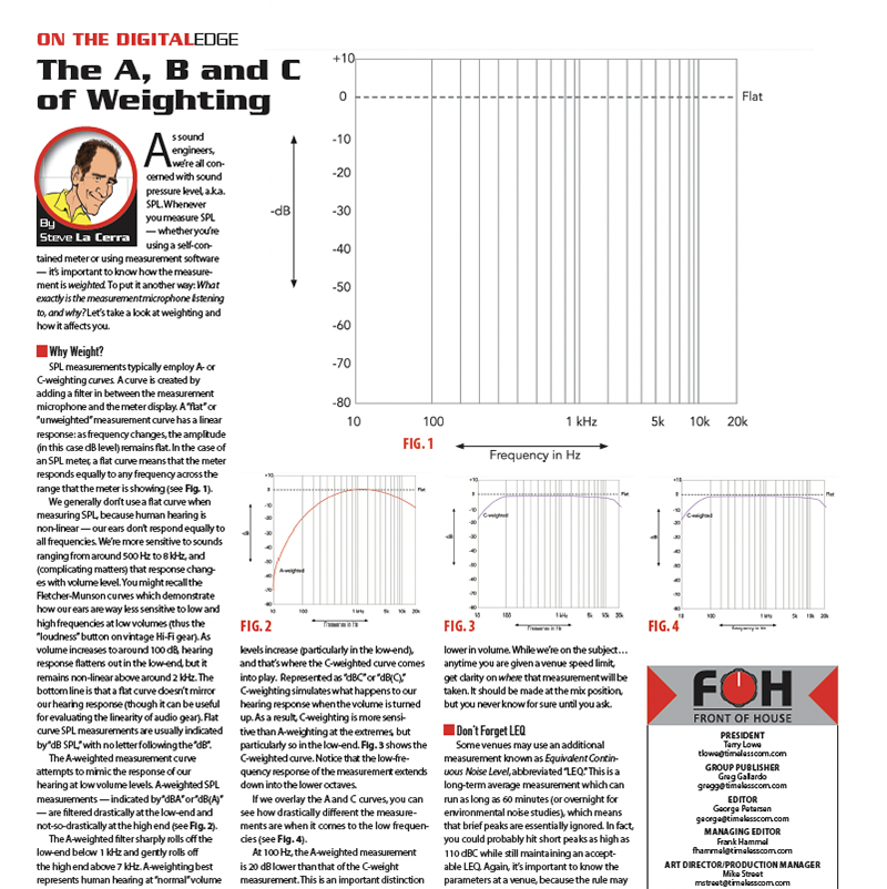
In the days immediately prior to this year’s James Taylor tour, I cajoled my nephew Gabe Morgan into helping me move the DiGiCo SD5 console out of my living room and out to the garage for pickup. I then I traveled to New York City where James and his band were performing at a private event that took place in the Marriott Marquis Hotel in Times Square. For this show, I would be using the familiar Avid D-Show desk for the final time this year. The band configuration was the same as it was for our final 2013 show in Honolulu, and I could quickly recall that complete setup from USB drives. Under the time constraints one encounters working this type of event, that strategy was definitely the best available option. The show went very well, but I was eager to move forward with the process of changing console platforms.
The next stop would be at Clair Global in Lititz, PA, where monitor engineer Rachel Adkins and I would spend two days of prep work before heading to Portland, OR to start the tour. Upon our arrival, we were greeted by Clair’s chief digital console technician, Tom Butson, who led me through the warehouse to the DiGiCo SD5 console I would be using this year on tour.
Connections
Clair had created a single rack containing two Avid VENUE stage racks and two DiGiCo SD racks plus two Clair 40-pair splitter systems. This large rack allowed Rachel and myself to patch the show in Lititz and have it remain in that finished condition for the remainder of our USA tour.
While working with the SD5 in my living room, all input information was derived from a multitrack recording stored on my laptop. The 48 multi-track outputs were routed to the SD5 through a DiGiCo UD MADI interface. I now had to learn about interfacing transducer inputs via the two SD Racks on stage that connected to the SD5 via the Optocore fiber optic network. My first task at Clair was to load the session I had created at my house. The console’s structure and surface layout that I had previously configured would remain unchanged but all the inputs needed to be reassigned.
After connecting the Optocore fiber optic network connectors between the console and the SD Racks, it is necessary to open the Audio I/O window found under the Setup tab on the Master Screen in order to identify and link to the various devices to which the SD5 is interfaced. There are a series of precise steps one must perform to successfully marry the multiple ports on the console to the stage racks and the Pro Tools recording rig.
Throughout this process, I needed frequent direction and help from both Butson and Steve Callebert, who is also on the Clair console staff, and my good friend, Dave Skaff, who guided me through the Pro Tools setup. The DiGiCo system setup is truly elegant and incredibly versatile but the initial configuring process is very specific and requires diligence in executing the necessary actions. Having an experienced guide to augment what is contained in the user manual vastly speeds up both the learning and setup processes.
 I/O Channel Assignments
Once the Optocore network has been initialized and the various I/O ports have been properly configured, the console’s Master Screen/Setup/Audio I/O selection (shown in Fig. 1) presents a graphic display that lists each I/O device connected to the SD5 through its multiple ports and the operating status of each connection. Selecting a single device port displays a grid corresponding to the various I/O cards and sockets of that unit. As each input socket is subsequently connected to an input or output channel strip, the name applied to that strip is simultaneously displayed on the corresponding socket of the I/O device.
Unlike Avid or Yamaha, DiGiCo does not use a pin matrix-type system for input/output patching. Instead, the SD5 system allows the user to first create a custom fader layout on each layer (2) and bank (5) that comprise the three bays of 12 faders on the control surface. Rather than making up a conventional input list and then moving things around until an intelligent and ergonomic work surface layout has been achieved, DiGiCo software allows one to start with the fader layout and then easily attach inputs from the sockets on the SD Rack. I experimented with several combinations of inputs, outputs and effects returns before settling on the layout I knew I wanted to employ. This particular design feature was instrumental in creating a favorable first impression when I began the search for a new console system.
Having previously created the most advantageous topology at my home in California, it was time to begin the actual assignment actions. Touching the top of any channel strip opens a channel setup window. Touching the button marked “Main Input” opens a second window in which one selects an input number from the cards contained in the SD Racks. Coming from my many years of managing individual channel strips on analog desks, I found this method to be the easiest way to develop an understanding about this method of input patching. However, the same tasks can be performed from a window opened by selecting the Master Screen/Layout/Channel List. In either case, one must have an input list close at hand to determine which of the stage inputs has been assigned to a given socket on the SD Racks.
 The Channel List
Choosing the Edit mode gives one access to all the I/O possibilities for a given channel strip. The Channel List display in the Layout menu (see Fig. 2) offers a complete list of all the input, aux, group, matrix and control group channels that exist within the session. Each channel’s list type can be expanded and collapsed by touching anywhere in the channel type’s row and can be distinguished from the specific Channel rows by their slightly darker color.
This screen is the most powerful area for user interaction with the console. Each aspect of channel functionality may be accessed here. As a new user, I found it easier to route signal via the pop-up windows opened by touching the associated areas on the individual channel strips. But now, having gained familiarity with the SD5 surface and its software, I will be using this area for setting up future projects.
After investing the time to learn the DiGiCo system and software management, I can honestly say that the SD5 control surface is the most user-friendly large-format console I have encountered. I am particularly appreciative of the versatility of the control surface. For example, a single input may be assigned to multiple faders. I have placed James Taylor’s vocal mic input as the first channel strip on each of the five banks of Layer One on the right hand fader bay. This simple feature keeps that critical fader always available while navigating through multiple input banks I need to access during the show.
One fantastic development took place just before I arrived in Portland, OR, for the first stop on this year’s tour. DiGiCo and Waves released a software update that expanded the SD5’s system capability from 16 Waves rack bays to 32. DiGiCo’s Matt Larson flew out to Portland to install the upgrades and get me up and running with the latest revisions. This extended capacity has allowed me to augment the onboard software with many of my favorite Waves devices and helped to retain much of the flavor and subtlety that characterized the shows we have performed in recent years.
Next month I am going to go through my Top 10 list of features that have made me a SD5 true believer and satisfied user.
Safe Travels!


